
PROJECTS
TyreWiz 2.0
Reinventing Tyre Pressure for the Modern Rider
When SRAM wanted to bring pro-level tyre pressure sensing to more riders, they came back to us after our collaborative success with ShockWiz, a category-defining suspension tuning system.
From firmware and electronics to precision test rigs and factory integration, we helped make TyreWiz 2.0 possible.


Goals
SRAM wanted TyreWiz 2.0 to be slimmer, more affordable, and ready for OEM integration on new bikes. The new housing mounted flush to the rim, reducing visual bulk.
At the same time, cost reduction was key. We helped cut the bill of materials and assembly cost by 40%, making the product viable for wider adoption across SRAM’s OEM partners.
New Pressure Sensor and Power Supply
The original sensor was precise but overspecced. We sourced a lower-cost alternative that matched performance specs and had global availability. The new sensor needed a different power supply, and due to the 2021-22 chip shortage, the original ADC chip was unavailable.
We removed it entirely, building new firmware around the microcontroller’s internal ADC. This reduced complexity and cost, with increased firmware engineering effort offsetting the hardware gains.


Circuit Board Design
The mechanical design was led by Quarq, including the flush new form and airflow path through the valve stem. We received a fixed board outline and designed circuitry to suit.
We also helped design the battery spring terminals, verifying fatigue resistance using ANSYS FEA. This collaboration ensured a tight integration between mechanical and electrical systems from the outset.
Test Jig Validation
Sealing performance with an O-ring couldn’t be simulated, so we developed a test prototype without a microcontroller to evaluate the sensor in a controlled housing. We emulated the sealing face and structural fixings with a CNC machined shell, enabling pressure and thermal tests.
We used in-house precision instruments to verify noise and signal quality across pressures. Results showed our microcontroller-based ADC design was more than sufficient.


Antenna and Layout
We faced an antennae layout challenge: due to packaging constraints, the Bluetooth chip antenna had to sit opposite the rest of the circuitry. We overcame impedance matching and RF tuning difficulties through advanced PCB layout, precise copper layer selection and trace tuning.
The battery was integrated as part of the ground plane, improving RF consistency. We tuned the antenna so it remained reliable in its final embedded environment.

Manufacturing Challenges
The BGA microcontroller used one of the world’s smallest pitch layouts, and we chose 0201 passive components to minimise board size. This required new pick-and-place nozzles, ultra-fine solder paste, and extremely tight stencil tolerances.
Our early attempts using a reflow oven yielded only 3 working units, so we upgraded our in-house PCB assembly line with a vapor phase oven, achieving 100% yield and enabling consistent production of the compact design.
Fixtures and Test Systems
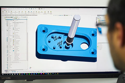
We supported two major production fixtures. For the FTF (Functional Test Fixture), we wrote the software to operate their supplied hardware. Separately, we developed a full calibration fixture from scratch.
We designed the system in SOLIDWORKS, including pneumatics, regulators, and electronics. CNC machining was used for precision. This fixture made line calibration fast, repeatable, and self-contained.


Assembly and Production
We produced the first P5 prototype batch of around 50–100 units. Quarq 3D printed the housings and we assembled and shipped them for environmental testing. We also delivered earlier P4 board runs for parallel evaluation.
A Taiwanese manufacturer later built a large P3 batch with injection-moulded housings. We travelled to Taiwan, delivered the fixtures, and supported first-line production, enabling hundreds of devices to be assembled on-site.
Integration and Validation
We continued firmware development and CI validation using our in-house calibration fixture, which remains in use for integration testing. It automatically validates each firmware update against known-good units.
The fixture replicates both functional and calibration tasks, providing traceability and test logs for remote teams. This robust system ensures SRAM can update firmware without risk of field failures.

Product Acceptance
We conducted extensive ride testing on pre-production P2 and P3 units, validating pressure readings, performance range and user interaction. This ensured real-world reliability.
Our team also implemented ANT+ communication, enabling the devices to stream pressure data to compatible bike computers using industry-standard protocols.
The Result
TyreWiz 2.0 was a technical and commercial success. The redesigned product met SRAM’s performance and cost goals, opening the door to high-volume OEM integration and broader consumer access.
With fixture support, CI infrastructure and robust firmware in place, TyreWiz 2.0 continues to perform reliably at scale.
